|
4. Remove the printed circuit board
To remove the PCB you need to unscrew several screws and unsolder the head wires.
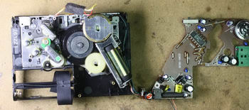
The position of these screws and head wires is marked on the images below. I made photos for WM-DC2, WM-DD100 and WM-DD. Procedure is almost the same for these models.
Before you start with removal, mark the position and solder point of each wire. Otherwise it is possible that after manipulation, some wires might break loose and you will not know where they belong. These are usually wires coming from the battery (orange, black), motor (black, red or white, red), two wires from FG coil (black) and wires coming from the switch (blue, violet) and grey wire coming from the head, with two or three wires inside (white-L, red-R and optionally yellow). You can also take photos. I prefer a simple drawing.
Here is the PCB removal procedure:
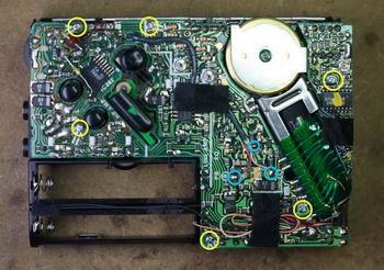
- Remove the black sticky tape holding the grey head wire.
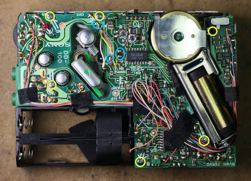
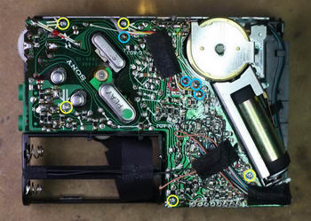
- Unsolder the head wires from the PCB (marked blue on the images). They’re marked on the PCB either by color (letters R W Y) or by channel (letters L R C). In cases when they aren’t marked you have to draw their positions in advance. Also, unsolder the ground wire and mark its location.
- Disconnect the orange and black wires from the battery holder. Either unsolder them from the PCB or from the battery holder - push down the flat sheet with orange wire and pull out the spring minus pole with the black wire.
If possible try to leave the black sticky tape, holding all wires together, where it is. It secures all wires and minimizes the risk that wires will be accidentally disconnected from the PCB.
Another option is to remove the black tape and leave the orange and black wires connected on both sides. But I do not recommend this, because sooner or later one of these wires will break loose from the PCB or holder.
- Unscrew all screws (marked yellow on the images)
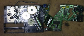
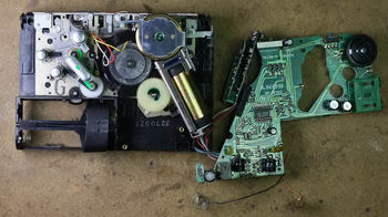
- Flip the PCB
WM-DC2
WM-DD100

WM-DD
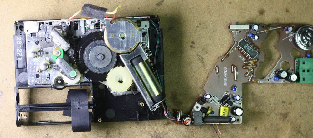
Get access to the broken center gear
In order to remove the center gear from the mechanics, several other parts need to be removed first. In this guide detailed removal instruction of these parts will be described.
Transport buttons removal
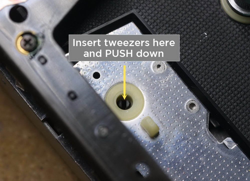
To remove the buttons, they must be pulled out. Ensure that the walkman is in stop position. Catch each of the buttons firmly with your fingers and pull them out one by one. You can use a little force to do it.
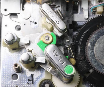
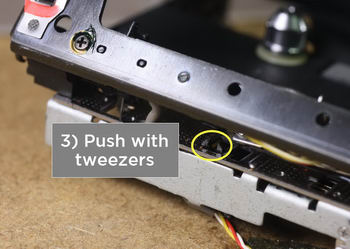
Only the STOP button requires more attention. From the cassette compartment side, locate the hole into which this button is inserted. Push the black plastic 'something' with tweezers while pulling the STOP button out.

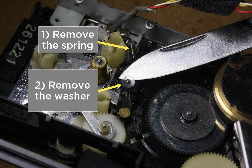
Slider removal
The plastic slider is used to move the head block up and down. This part is marked in blue on the following image.
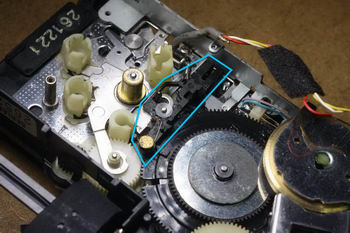
To take it out, you have to remove:
- The small spring.
Use precision tweezers to remove it. Warning: it tends to shoot out while you remove or install it.
Tip: always hold the other hand over it while trying to remove it - if it shoots out, you will at
least know where to look for it.
Remember how it is positioned, you will need it when assembling it back!
- The washer.
Use the pocket knife to remove it. Warning: It too tends to shoot out while you remove or install it.
Tip: Again, hold the other hand over it while trying to remove it.
- The slider itself.
Push it from the side of the cassette compartment. Never try to remove it from the
mechanics side - or you may break it.

|